If you saw my first post regarding my attempts to use a DLink DIR-825 with FreeBSD, you noted that I was busily trying to get the serial console working. I won’t go over the reasons for it in this new post, but get straight into the fun and games.
My motivation here is to make the serial console available without ripping open the case every time there is an issue. FreeBSD in a OpenWRT/DD-WRT style configuration is a very open universe right now and there will be lots of changes to come.
For now, let’s start with the ingredient list:
- DLink DIR-825 rev. B1
- Soldering Iron, solder, solder braid, good tweezers, scissors, exacto-knife
- Jumper wire leads, F-F
- OSEPP FTDI Breakout Board kit
- Circuit Board safe superglue
Step 1 of this operation is to open the DIR-825, remove the main board and solder on pins to JP1 on the board.
Once that is secure and you’ve validated that you can use your USB TTL adapter to get a serial console then you can move forward to setup the internal mounting and give yourself an external connector.
The case is used in 2 and 3 antenna models. This unit leaves us the center antenna mount as a very convient place to secure our TTL USB adapter. Get your exacto-knife and cut out the black label area covering this hole. Then gently cut out the top half of the innner plastic ring as I have shown in this photo.
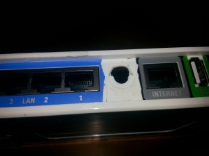 See how nicely the USB connector presents itself? Its as though we planned this out!
Next, I modified the TTL adapter itself. I needed to remove the jumper at the center of the adapter as it collides with the capacitor directly adjacent to the mounting point.
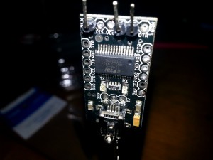 I then was able to solder a very small length of wire to short the 3.3v selector permanently. You’ll need a steady hand and the tweezers to pull out the pins and insert the wire.
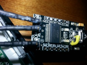
You’ll note that I’ve removed the pin header that comes with the adapter. This was accomplished with a sharp pair of scissors and then using the soldering iron to extract the remainder of the pins with judicious use of tweezers.
Once that was done, I soldered on individual pins for TX, RX and ground. Note that I’ve bent the pins at a 45 degree angle. This will avoid any issues with the pins making contact with the mainboard.
Now that you have all the pieces ready to go, its time to break out the superglue and mount the thing. When choosing a glue, you’ll need to get one that is safe for PCB and plasitc in general, your local electronics and hobby shop can direct you to the proper stuffs.
I mounted the TTL adapter upside down so that the connector can reach the opening on the case and there are two lower points of contact for the glue to set correctly.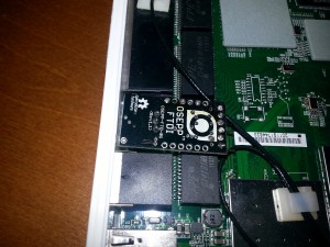
I applied glue to the two corners next to the USB header, flipped it over and brought it into firm contact with the antenna mount. After about 1 minute, I released pressure and applied a line of glue across the surface of the TTL adapter such that it sealed against the case of the router.
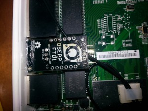 Now … WALK AWAY for at least 6 hours. If you’re using the right kind of glue, there’s some science happening here and you need to let the glue/plastic cure to get a secure mount.
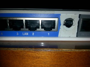
Wire up your TX, RX and ground leads, reattach the case housing and connect up your new USB serial interface to a PC. On FreeBSD, you should see a new serial port appear.
ugen5.2: <FTDI> at usbus5
uftdio0: <FT232R USB UART> on usbus5
Go ahead, open it with your handy, dandy comm utility, cu:
cu -l /dev/ttyU0 -s 115200
If you’ve done everything right, congrats, you’ll now see the embedded linux distribution boot up. You are now at Step 0 getting your FreeBSD based home router running.